
Describe what the poles do
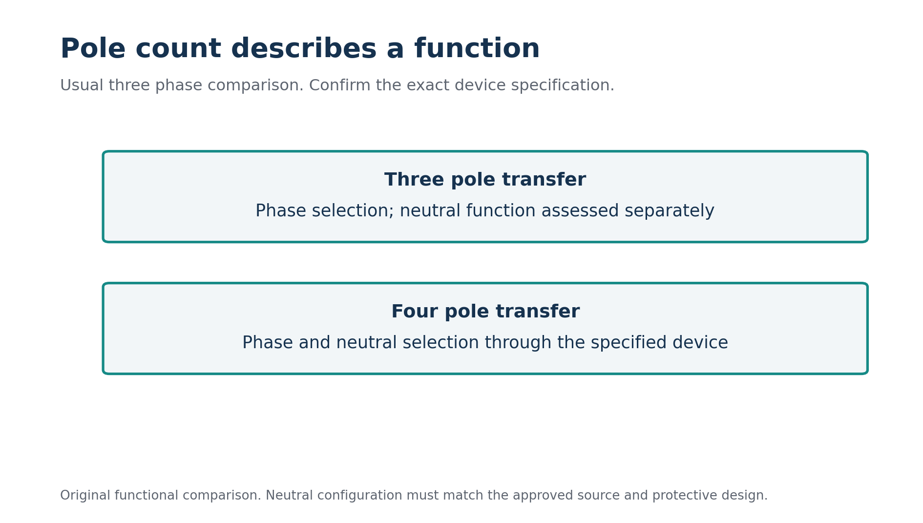
In the usual three phase changeover comparison, three poles transfer the three phase conductors. A fourth pole can transfer the neutral as well. The important difference is therefore the neutral connection through the operating states. This functional explanation should be checked against the actual device diagram and specification rather than inferred from a photograph. [2]
A solid neutral arrangement maintains a continuous neutral connection through the transfer assembly. A switched neutral arrangement uses an additional switching pole to select the relevant source neutral. ASCO also describes overlapping neutral arrangements with a particular contact sequence. These terms identify different functions, and overlapping neutral should not be treated as another name for every four pole device. [3]
Pole count does not describe every aspect of the equipment. It does not tell you the transfer sequence, contact ratings, controller behaviour, permitted source synchronisation or protective coordination. Read the complete product reference. Two devices with the same number of poles can still behave differently during transfer.
Start with a source inventory
For the fictional hall, identify the normal supply and the standby generator. Record their voltage arrangements, neutral availability and the earthing and bonding information needed by the designer. Also identify where the transfer device sits in relation to the incoming boards, protective devices and selected loads.
Do not assume the generator's factory configuration describes its final installed arrangement. The supplied equipment information and the approved project design must be reconciled. Likewise, do not infer the normal supply's complete protective arrangement from the presence of a neutral terminal at one board. Trace the relevant connections using verified documentation.
List any additional sources, such as another generator, storage system or photovoltaic equipment that can affect the arrangement. Then describe which sources can supply which loads. A transfer review that considers only two sources may be incomplete if another connection creates a credible operating state elsewhere in the installation.
Finally, identify the loads. Some need only a running power allowance; others may have continuity, starting or neutral related requirements. A lift, electronic control system and simple lighting circuit should not be treated as identical loads because they share a supply board. The transfer design needs the relevant equipment information and operating expectations.
Separate neutral from protective conductor functions
The neutral and protective arrangements must be identified by function. A conductor carrying normal return current and a conductor providing a protective connection have different roles. Combined conductor arrangements introduce further questions. Colour or a shorthand label cannot replace verification of the actual function at the point being assessed.
Create a conceptual source diagram for review, showing the source neutral connections, relevant bonding points, protective connections and load neutral route. Keep it separate from a construction drawing until the design is established. Its purpose is to expose questions that a simple transfer symbol can hide.
For each proposed device, ask which connections exist with the normal source selected, with the standby source selected and during transfer. Then ask whether those connections agree with the intended earthing and fault protection arrangement. This physical review is more informative than repeating a slogan about generators always needing one particular pole count.
The answer depends on the actual design and applicable Israeli requirements. Do not import a foreign code's source classification or wiring rule as an automatic local instruction. Manufacturer application material can explain concepts while the responsible professional establishes the jurisdictional requirements and approved arrangement for the project.
Review the transfer states explicitly
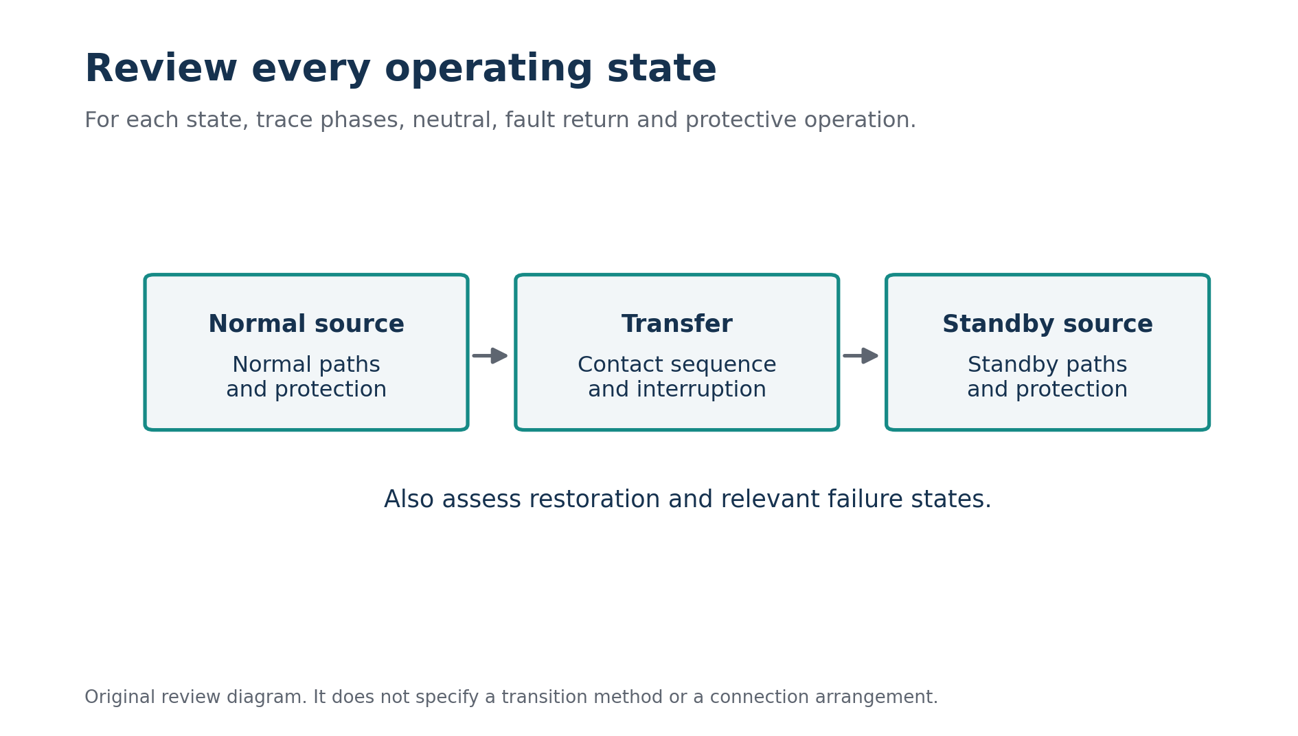
Use a state record rather than a single static picture. The hall's first state has the normal source supplying the selected loads. The second has the standby source supplying them. The third describes the transition between those states. For each, identify the active phase path, neutral arrangement and protective assumptions.
Review the operating and protective paths during normal supply, transfer and standby supply. Original concept diagram.
If the proposed transfer is open transition, establish the specified interruption sequence and how the neutral contacts behave. If another transition method is proposed, obtain its exact description and required source conditions. The word “automatic” describes control action; it does not describe whether sources overlap or whether the neutral remains connected.
ASCO's descriptions distinguish a switched neutral sequence from an overlapping neutral sequence. That distinction illustrates why a diagram needs time information as well as connection information. The relevant contact operation must be confirmed for the selected equipment rather than borrowed from a different transfer switch family. [3]
Ask what happens if the normal source fails in an unusual way, the standby source is unavailable or the controller loses its required supply. The answers come from the device and system design, not from its pole count. Record the expected operating behaviour and any limitation that affects the loads or protective arrangement.
Follow the fault return path in each state
After drawing the normal operating paths, examine the protective paths for the relevant faults. A change in source can change the available fault current and the route back to that source. A protective device selected using only the normal supply conditions may require another assessment under standby operation.
In the fictional hall, imagine the normal source provides a fault level that readily supports one protective assessment, while the generator's available current behaves differently. The design review needs the appropriate generator data and protective characteristics. A transformer terminal calculation cannot simply be reused as a generator fault calculation. [4]
The neutral arrangement can also interact with residual current sensing and bonding connections. Trace the relevant monitored conductors and return paths in the actual proposed system. Identify unintended parallel paths or connections that would undermine the intended protective explanation. Do not diagnose their presence from a generic diagram that does not represent the project.
For a study exercise, compare two supplied conceptual arrangements and describe their paths. Stop short of declaring a real wiring solution without the necessary source and regulatory information. A strong answer identifies what must be known and explains why each missing fact affects the choice.
Compare proposals with the same questions
Ask both suppliers to identify the exact product, pole configuration, neutral function, transfer sequence and relevant ratings. Request the manufacturer's operating diagram and installation information. A brochure headline such as “four pole automatic transfer” leaves too many functional details unstated to support a complete comparison.
Then compare the equipment against the hall's established design. Does the device implement the required neutral behaviour? Are its ratings appropriate to the supply and load conditions? Does the control sequence match the operating requirement? Is the proposed arrangement compatible with the protective design and required verification?
Keep a separate list of unresolved information. One proposal may include a clear neutral diagram but omit a relevant rating. Another may provide extensive ratings but leave the contact sequence unclear. Neither omission should disappear because the supplier is familiar or the quoted price is attractive.
Avoid deciding the neutral function from cost alone. A cheaper device that performs the wrong function is not an equivalent offer. Once functional suitability is established, commercial comparisons become meaningful. Before that point, the proposals may describe different technical arrangements even if they appear beside one another in the same purchasing table.
A useful supplier clarification can focus on one disputed detail. Suppose an offer includes a neutral terminal but does not identify whether that terminal is connected through switching contacts or a continuous connection. Request the specific operating diagram and match its terminal labels to the offered product reference. The presence of a terminal does not establish its behaviour during transfer. Then record the answer beside the original requirement, so the clarification becomes part of the comparison. This method keeps the discussion concrete and prevents a broad assurance that the switch is suitable from replacing the functional evidence needed to assess the proposal against the hall's established source and protective design.
Document load continuity realistically
Standby supply and uninterrupted supply are different operating expectations. A transfer system may involve a period with no normal load supply while the standby source becomes available and transfer occurs. Establish what each critical load can tolerate and whether additional equipment is needed to meet its continuity requirement.
For the fictional hall, separate emergency lighting requirements, control system behaviour and noncritical ventilation. Do not promise that every electronic device will keep running merely because the installation includes a generator. The equipment's restart behaviour, transfer timing and relevant requirements belong in the load review.
Record the intended restoration sequence as well. Returning to the normal source can create another interruption or operating event. Operators need to know the expected behaviour, and the designer needs to assess the relevant state. A transfer review is incomplete if it explains the move to standby but ignores the move back.
Prepare verification before commissioning
The verification plan should be developed from the established design and manufacturer instructions. It needs to address the selected source states, the intended transfer operation and the protective arrangement. A successful demonstration that the generator starts does not establish every electrical and functional requirement of the transfer system.
Useful commissioning records identify the installed device, settings, source arrangement, relevant test results and observed operating sequence. Any discrepancy between the drawings and installed connections should be resolved through the responsible design and installation process. A marked up diagram is evidence of a change that needs review, not permission to leave a conflict unexplained.
Training and maintenance records should describe who may operate the system, what indications mean and how reported problems are handled. The technical design can be sound while the operating information remains inadequate. A clear handover connects the approved arrangement to the people responsible for its ongoing use.
Revisit the design when the installation changes
Adding loads, replacing a generator or introducing another source can change the assumptions behind the original choice. Keep the source diagrams and transfer records available for later review. A pole count selected for an earlier arrangement is not a universal property of the building.
Suppose the hall later adds a storage inverter. The review should establish its operating modes, source connections and interaction with the existing transfer system. Do not simply attach it to a familiar point on the old diagram. The credible supply states and protective paths need to be reconsidered together.
The same principle applies to replacement equipment. A new four pole device may have a different neutral sequence from the previous four pole device. Matching the label does not establish functional equivalence. Compare the complete specification carefully and verify the arrangement after the replacement.
Explain the final choice through the diagram
A defensible answer to “three pole or four pole?” begins with the source and protective design. It explains the required neutral function, identifies the operating states and shows how the selected equipment implements them. It also identifies the local requirements and verification supporting the decision.
For study, practise giving that explanation without declaring that one pole count is always superior. The goal is to connect device behaviour with an actual system. Once the neutral route, source bonds, fault paths and transfer sequence are clear, the pole count becomes a consequence of the design rather than a guess made at the beginning.
מקורות והפניות
המקורות המוזכרים בגוף המאמר מופיעים כאן כפי שנמסרו במקור.
- [1] Nami Academy: 3p/4p changeover tool
- [2] Schneider Electric / ASCO: transfer mechanism components
- [3] Schneider Electric / ASCO: neutral configurations
- [4] Schneider Electric: generator protection
רוצים לתרגל את הנושא?
אחרי הקריאה אפשר לעבור למבחן או למדריך הקשור לנושא.