
Distinguish normal current from fault current
In a simplified single phase load, normal operating current leaves the source through the line conductor and returns through neutral. The protective conductor serves a different function. Treating it as an ordinary return conductor confuses both the circuit model and the purpose of the protective arrangement.
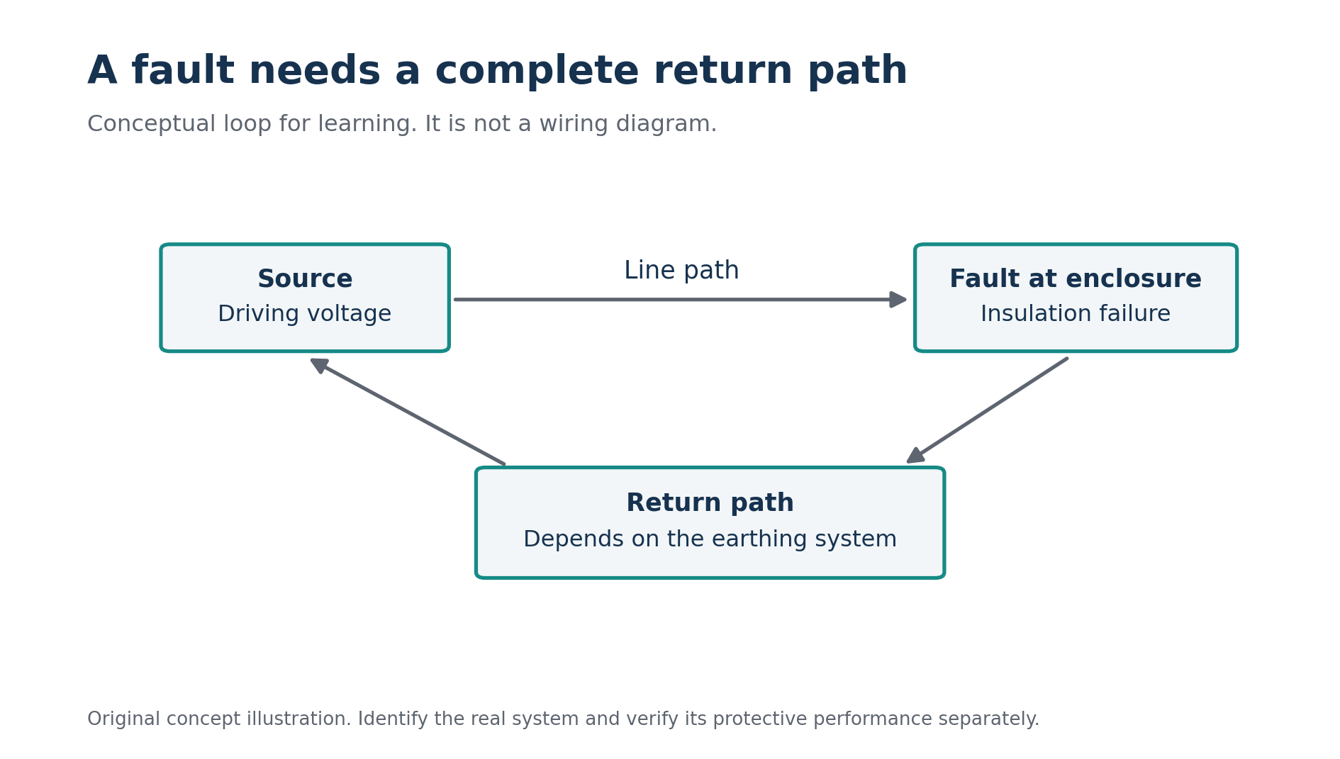
When insulation fails between a live conductor and exposed conductive metalwork, the fault can create a different return route. The relevant path depends on the earthing system. Draw the complete loop conceptually, including the source connection, rather than stopping at an earth symbol. A symbol represents a connection; it does not explain its impedance or continuity.
For study, use a supplied diagram and colour the normal path separately from the fault path. Then write the name of every conductor or connection included in the second route. If you cannot complete the route back to the source, you have identified a gap in your explanation. Resolve that gap before choosing a protective device from memory.
Understand the TN principle
In the TN principle, exposed conductive parts are connected through the protective arrangement to the source's earthed point. A line to enclosure fault can therefore have a predominantly metallic return path. Whether the protective device disconnects as required depends on the complete loop and the device characteristics. The TN label alone does not establish the result for an actual circuit. [2]
Take a fictional training model with a 230 volt driving voltage and a complete fault loop impedance of 0.8 ohm. The simplified current estimate is 230/0.8 = 287.5 amperes. Change the assumed loop impedance to 2 ohms and the estimate becomes 115 amperes. The examples illustrate why the condition of the full return path matters.
Neither number proves a disconnection time. To answer that question, compare the relevant fault condition with the selected protective device's verified behaviour and the applicable requirement. A learner should explain this remaining step explicitly. A large looking current is evidence for a calculation, not an automatic statement that protection has been demonstrated.
Avoid using TN, TN-S, TN-C and TN-C-S as interchangeable labels. They describe different conductor arrangements. An existing installation's drawings and verified connections must establish which arrangement exists at each relevant point. A photograph of one green and yellow conductor cannot describe the entire source and distribution system.
Understand why TT requires another perspective
In a TT arrangement, the installation's exposed conductive parts connect to its earthing arrangement, while the source has its own earthing connection. The earth fault loop can include the installation electrode, soil and source electrode. That path can limit fault current enough that ordinary overcurrent protection alone does not provide the required fault protection; residual current protection has a central role. [3]
Use a deliberately simplified training loop of 46 ohms at 230 volts. The resulting current estimate is 5 amperes. The arithmetic is straightforward, but its meaning differs from the low impedance TN exercise. A fault to an enclosure can be serious even when its current is smaller than a circuit's normal load rating.
This comparison explains why “the breaker did not trip” does not prove that no dangerous fault exists. Protective functions respond to different quantities. The relevant system must be assessed through its complete design, including earthing, bonding, residual current protection and the applicable operating requirements. Do not infer an approved electrode resistance from this fictional loop value.
Explain residual current without a slogan
An RCD compares the currents passing through its sensing arrangement. In normal operation, their signed or vector sum should balance apart from leakage and related effects. Current returning by a path outside the monitored conductors creates a residual quantity. The device responds according to its characteristics when the relevant operating conditions are reached. [4]
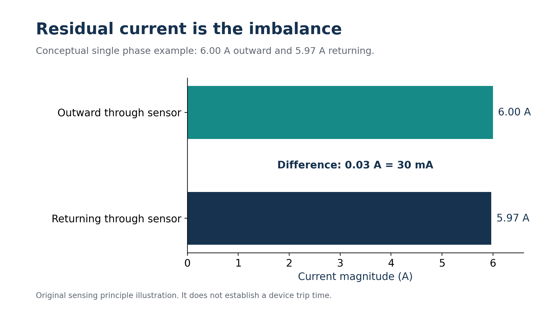
Consider a conceptual single phase example. Exactly 6 amperes pass outward through the monitored line conductor, while 5.97 amperes return through the monitored neutral. The difference is 0.03 ampere, or 30 milliamperes. That difference is the residual in this simple illustration. It is not the six ampere load current converted into a smaller unit.
The numbers explain the sensing principle rather than the guaranteed operating time of a particular device. A real response depends on the device specification, waveform, residual magnitude and relevant conditions. Keep a calculation of the imbalance separate from a claim about a measured trip time. Each requires different evidence.
The simple sensing example has a 30 milliampere imbalance. Original chart; it does not establish a trip time.
Now imagine that all the current returns through the monitored neutral even though the load current is excessive. The residual can remain approximately zero in the simplified model. That is why residual sensing and overload protection cannot be treated as the same function. Identify what each device actually measures before explaining why it should operate.
Read the device functions and markings
A conventional RCCB provides residual current protection without integral overcurrent protection. An RCBO combines residual current and overcurrent functions. The product designation, applicable specification and coordination with other equipment matter. The familiar appearance of a device or the presence of a test button does not establish which protective functions it contains. [5]
Distinguish rated current from rated residual operating current. A fictional device marked with a 40 ampere current rating and a 30 milliampere residual rating has two different quantities describing different aspects of its operation. The 40 ampere number should not be described as its residual trip threshold, and the milliampere number is not the circuit's permitted normal load.
Selection also involves the residual current waveform and the connected equipment. Electronic loads can require consideration of characteristics beyond a generic sensitivity figure. Record the exact device type and consult the applicable manufacturer information. A training answer should identify the relevant selection question even when the exercise does not supply enough information to complete it.
Where several residual current devices operate in a hierarchy, coordination deserves a separate review. A downstream fault should not be assumed to leave every upstream circuit energised just because two devices have different labels. The actual characteristics and arrangement determine the outcome. Document the intended behaviour and the evidence supporting it.
Keep earthing, bonding and additional protection distinct
Earthing, protective bonding and residual current protection contribute different parts of the protective arrangement. Their functions need to work together. An RCD does not repair a broken protective conductor. Equally, a visible protective conductor does not establish that a selected RCD is suitable or that its required performance has been verified.
Protective bonding addresses the relationship between relevant conductive parts. Identify the parts and connections required by the applicable installation rules rather than attaching an earth label to every metal object in a photograph. The purpose of a training explanation is to describe the protective relationship, not to invent a bonding schedule from appearance alone.
High sensitivity residual current protection can provide additional protection, but it should not be described as complete protection against every form of contact or every fault. Schneider Electric's guide treats it as an additional measure within a broader protective system. That distinction matters when explaining why sound insulation and the required protective arrangement remain necessary. [6]
Interpret testing evidence carefully
The test button and a professional installation test answer different questions. A successful button operation does not prove protective conductor continuity, electrode performance or the complete installation's compliance. Treat each test result as evidence for the specific function and conditions it addresses, rather than as a certificate for the entire circuit.
Follow the device instructions and applicable local requirements for routine checks and test intervals. Schneider Electric explicitly advises that intervals depend on local rules and operating conditions. Avoid publishing one universal monthly or annual interval without establishing which requirement applies to the equipment and installation being discussed. [7]
For a professional report, useful records include the device identification, circuit identification, test method, relevant measured results, acceptance criteria and unresolved observations. Preserve the conditions of the test as well. A bare “passed” entry makes it difficult to compare later results or determine whether equipment has changed since the assessment.
Learners can practise interpreting fictional test records without performing live work. For example, one record may show correct device identification but omit the test conditions. Another may document residual performance while saying nothing about the protective conductor. Ask what each record supports and what remains unproven. This develops a more useful skill than treating every positive result as interchangeable.
Investigate unwanted operation through evidence
Repeated RCD operation can have several causes, including equipment leakage, insulation problems, conductor arrangement issues or incompatible selection. A trip alone does not identify the cause. The correct response is a structured investigation by a competent professional, with the circuit and connected equipment considered together.
Create a fictional symptom record before attempting an explanation. Note whether operation follows one appliance, a combination of loads or a particular environmental condition. Record when the problem began and what changed beforehand. These observations narrow the questions that need testing; they do not justify bypassing protection or substituting a less sensitive device without assessment.
Avoid describing every unexplained trip as a nuisance. That word can imply that the protection is mistaken before the fault has been investigated. It is better to describe what happened precisely: which device operated, which loads were connected and what evidence is available. Precise observations support a useful diagnosis.
Present a complete protective explanation
Return to the fictional damaged appliance. A complete explanation identifies the source, the enclosure connection, the full fault return path, the protective function expected to operate and the verification needed to support that expectation. It also distinguishes the operating load current from the residual or fault current being assessed.
For examination practice, compare the same insulation fault in two supplied earthing diagrams. Explain why their return paths differ and what protective evidence each needs. Avoid memorising only device names. The stronger answer follows the physical circuit and connects it to the protective response.
Another useful classroom exercise starts with incomplete evidence. A maintenance note reports that an appliance operates normally and its RCD button disconnects the supply, but the note contains no protective conductor verification. Ask whether normal operation establishes that conductor's continuity. It does not: the appliance's ordinary circuit can work without demonstrating the separate protective path. Then ask what the button result establishes about the missing conductor record. Treat it as evidence about the device's test operation, not as a substitute for the absent verification. This exercise teaches a disciplined way to read a report. Identify the protective claim, locate the evidence that supports that exact claim, and leave unrelated evidence in its proper place. A professional assessment can then resolve the missing information instead of letting a reassuring observation conceal it from future reviewers.
Understanding earthing and RCDs means being able to tell that story accurately. Begin at the source, follow the normal circuit, trace the fault route and explain the selected protection. Identify the evidence supporting each protective claim separately. With those steps, the earth symbol and the test button become parts of a coherent system rather than shortcuts that conceal the questions a real assessment must answer.
מקורות והפניות
המקורות המוזכרים בגוף המאמר מופיעים כאן כפי שנמסרו במקור.
- [1] Ovrim Rishui: grounding and RCDs
- [2] Schneider Electric: TN system principle
- [3] Schneider Electric: TT system principle
- [4] Schneider Electric: description of RCDs
- [5] Schneider Electric: conventional RCCB functions
- [6] Schneider Electric: additional protection with high sensitivity RCDs
- [7] Schneider Electric: RCD test intervals
רוצים לתרגל את הנושא?
אחרי הקריאה אפשר לעבור למבחן או למדריך הקשור לנושא.