
Establish the load and the route
Start with the design current, usually written Ib. Record how it was obtained, including supply arrangement, electrical input rating, power factor and any relevant operating pattern. A motor schedule may also require starting information. A copied current value without its assumptions cannot reliably support the later protective selection.
Next, describe the route in segments. A cable may leave a board, enter trunking, pass through a wall and continue outdoors. Sketch the changes instead of describing the entire run as “on a tray.” Record the actual installation method, nearby circuits, thermal insulation, expected ambient conditions and termination constraints for the applicable assessment.
The route survey can also identify mechanical hazards, moisture, sunlight, chemicals and access requirements. These considerations affect cable construction and installation choices beyond current carrying capacity. A conductor area answers a narrow question. It does not tell you whether the complete cable is suitable for an exposed location or whether its enclosure offers the required protection.
Measure the cable route rather than the straight distance between equipment. Allow for vertical sections and necessary routing. Keep the measured length distinguishable from purchasing allowances. Voltage drop calculations need the electrical route length, while an order quantity may include additional material for handling and termination. Confusing these records creates avoidable discrepancies.
Coordinate the load, protection and conductor
A basic coordination relationship is Ib ≤ In ≤ Iz: design current, protective device nominal current or relevant setting, and the conductor's permitted current carrying capacity under its conditions. Protection also requires attention to the device's conventional operating current and its fault interruption capability. Schneider Electric's guide explains these checks within its IEC based framework. Applicable Israeli requirements must be established separately. [3]
The symbols describe a relationship rather than a shopping rule. Choosing a breaker just above the load current does not prove that the cable can carry that rating. Conversely, installing a larger conductor does not prove that a selected device has sufficient breaking capacity at the board. Each quantity has a separate evidence source.
In the workshop exercise, assume Ib is 28 amperes and the proposed protective rating is 32 amperes. The cable assessment must therefore establish at least the capacity needed for that protective coordination, together with the other required checks. A candidate with an adjusted capacity below 32 amperes does not become acceptable merely because the machine usually draws less than its design current.
Distinguish a fixed device rating from an adjustable trip setting. If the design relies on a setting, identify the device, permitted adjustment range, selected value and means of documenting it. An unexplained number written beside a breaker symbol can be misread during maintenance. Good documentation connects the calculation to the equipment actually installed.
Apply correction factors transparently
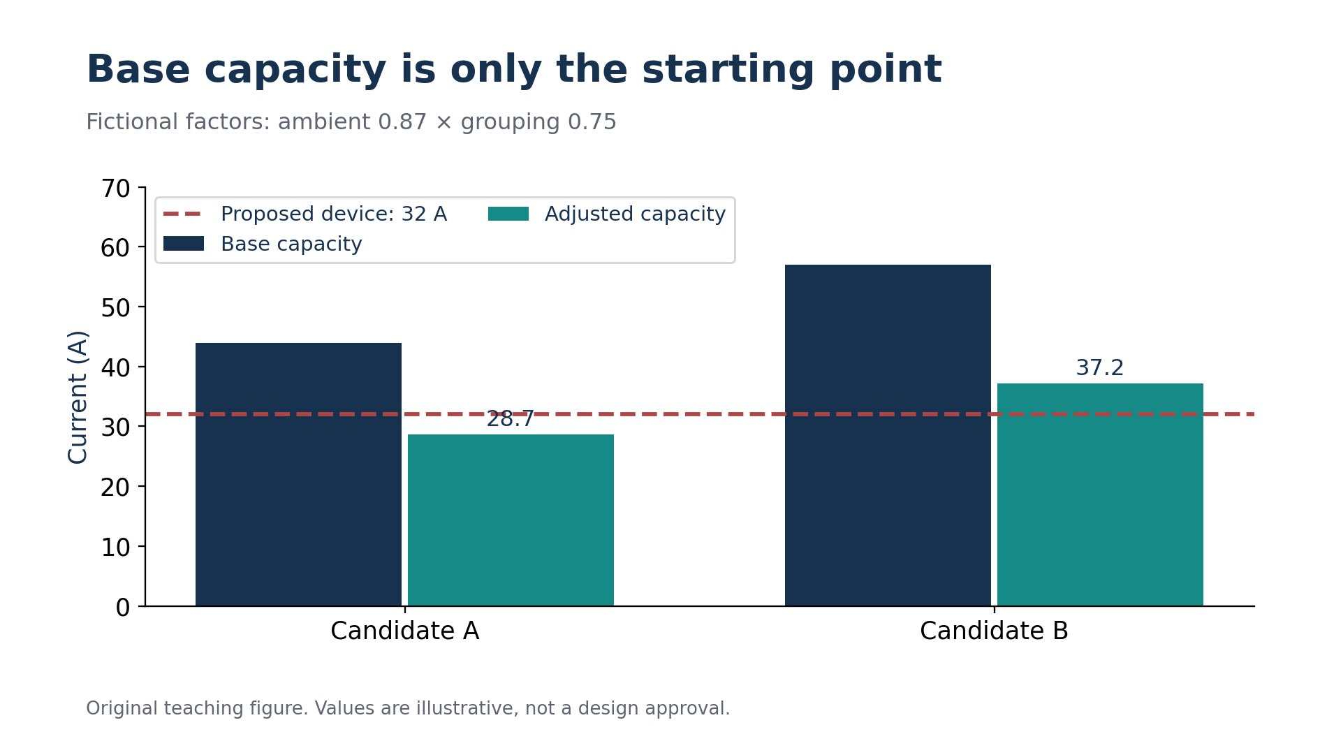
Assume a teaching table gives candidate A a base capacity of 44 amperes for a specified reference condition. Also assume the exercise supplies an ambient temperature factor of 0.87 and a grouping factor of 0.75, with instructions to multiply them. The adjusted capacity is 44 × 0.87 × 0.75 = 28.71 amperes. These factors are fictional inputs for this exercise.
That result exceeds the 28 ampere design current but falls below the proposed 32 ampere protective rating. Under the stated coordination test, candidate A fails. The lesson is easy to miss when checking only whether the conductor appears large enough for normal operation. Protection and conductor capacity must be considered together.
Candidate B has an assumed base capacity of 57 amperes under the same reference arrangement. Its adjusted capacity is 57 × 0.87 × 0.75 = 37.1925 amperes, approximately 37.2 amperes. It passes this particular thermal comparison with a 32 ampere device. It has not yet passed voltage drop, fault withstand, installation suitability or termination checks.
In a real assessment, obtain the reference capacity and correction rules from the applicable standard or manufacturer information. Some conditions require another table or a different evaluation rather than another multiplier. Record the table identification and the meaning of each factor. A string of numbers without their source cannot be independently reviewed.
Investigate the limiting route segment
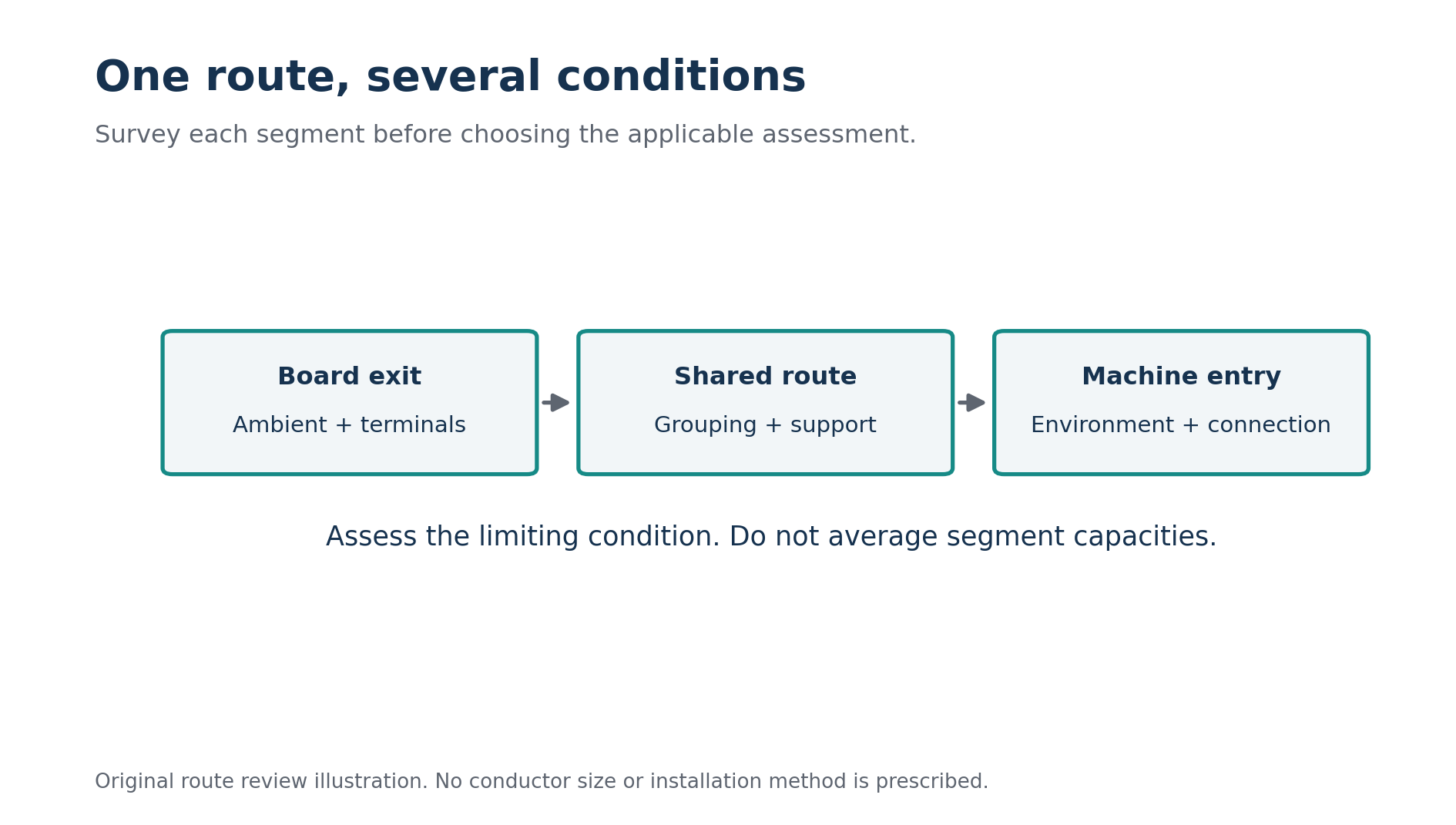
Suppose the cable runs openly for most of its length but crosses a short section with poorer heat dissipation. That section deserves its own assessment. Do not average two capacities simply because one installation method occupies more metres than another. The applicable rules must determine how the changed condition affects the permitted loading.
A useful route record names each segment and explains what makes it different. Segment one might use the reference arrangement. Segment two might include the grouped section. Segment three might experience the highest ambient temperature. This approach makes it possible to revise the assessment if the contractor changes only one part of the route.
A route survey identifies the conditions for each segment. Original conceptual illustration.
Consider an alternative for the fictional workshop: separate the new circuit from the existing group. If the exercise removes the grouping reduction while keeping the ambient factor, candidate A becomes 44 × 0.87 = 38.28 amperes. That comparison illustrates how an installation change can matter as much as a conductor change. It is not permission to apply a unity factor without verified conditions.
Compare alternatives using a short decision note. Explain what would change physically, which calculation input would change, and which other checks remain open. A larger cable may require larger terminals or more bending space. A different route may add length. Solving one constraint can create another, so review the complete proposal after each revision.
Check voltage drop separately
Thermal capacity and voltage drop are related through the conductor but answer different questions. A cable can remain within its thermal limit while losing too much voltage over a long run. The next article develops the calculation in detail. Here, the key habit is to treat voltage drop as a separate recorded check rather than assuming that the thermal result covers it.
Use the actual route length, relevant current, conductor resistance at the appropriate condition and any reactance and power factor terms required by the model. Include upstream losses when the applicable assessment concerns the complete supply path. State the permitted criterion and its source instead of borrowing a familiar percentage from another country's guide.
If voltage drop fails, compare justified options. Increasing conductor area, changing the route or reducing a verified demand may affect the result. Merely increasing the breaker rating does not reduce conductor impedance. A useful explanation links each proposed change to the quantity it actually influences.
Include fault duty and protective operation
Normal load checks do not establish performance during a short circuit. The design must consider prospective fault current, device interruption capability and the conductor's ability to withstand the clearing energy. It must also establish the required protective operation for the relevant fault conditions. These checks need information about the supply and protection, not just the machine nameplate. [3]
For a teaching review, imagine candidate B passes its thermal and voltage drop assessments, but the proposed breaker has an unverified breaking capacity. Mark the decision incomplete. Do not convert an unknown into a pass because the earlier calculations were successful. A complete result can contain several passed checks and one unresolved requirement.
Similarly, a fault current estimate at the main board may not describe a remote machine terminal. Cable impedance changes the fault conditions along the route. Maximum current is relevant to interruption and withstand, while a lower fault level can matter to timely protective operation. Keep the location and fault type attached to each result.
The protective conductor also needs its own assessment. Avoid treating the phase conductor choice as an automatic answer for every conductor in the cable. The applicable method, protective arrangement and fault conditions determine the necessary verification. For a real installation, this work belongs within the responsible licensed professional's design and testing process.
Use a calculator as a recorded calculation
Enter verified conditions into a tool only after preparing the input sheet. Nami's public page exposes several selection variables, which makes it useful for learning how changing conditions affects a result. Access and output availability may vary. Do not describe a result from a tool you have not actually run. [1]
When a calculation is available, preserve the inputs and the tool version or access date alongside the output. Review the assumptions behind its tables, especially temperature, insulation, conductor material and installation method. An output without those details is hard to compare with a manual assessment and even harder to revise months later.
Run a controlled comparison by changing one justified input at a time. For example, examine the effect of a different installation arrangement while holding the load constant. Explain why the capacity changes. Randomly changing inputs until a desired cross section appears teaches very little and can conceal a condition that does not match the site.
Finish with a decision that others can follow
The fictional workshop record should now distinguish candidate A's failed grouped thermal check from candidate B's provisional thermal pass. It should also record the alternative separated route and list the remaining assessments. This is more useful than announcing a winning size without explaining the conditions that produced it.
Before issuing a specification, reconcile the calculation with the final route, cable construction, equipment terminals and protective device. Any change to those items can require another review. Keep the supporting data with the drawing so procurement and installation teams can identify the intended product and arrangement without recreating your assumptions. Record the final assessment date and name the responsible reviewer, making the accepted conditions easy to locate.
One final review concerns the equipment connections. Suppose a revised proposal uses a conductor that will not fit the machine's supplied terminal. The thermal calculation has not authorised cutting strands away or improvising a connection. Record the incompatibility and obtain an appropriate connection solution through the equipment and installation requirements. Check material compatibility as well: a termination intended for one conductor material cannot simply be assumed suitable for another. The specified cable must be usable as a complete assembly, including its insulation, connectors, mechanical support and access for the intended work.
The handover record should also make later changes easy to assess. If a second machine is added beside the first, the original grouping assumption may change even though the original cable remains untouched. If ventilation is removed from an enclosure, its environmental assumption may also change. Attach a brief list of these design conditions to the circuit record. A future reviewer can then identify what needs recalculation before extending the installation. That small administrative step turns a successful calculation into a maintainable decision and reduces the chance that an old result will be reused for a physically different arrangement.
During study, practise explaining a rejected candidate as carefully as an accepted one. State the failed comparison, show the numerical evidence and propose a change that addresses that constraint. This develops judgement and makes your reasoning visible. Cable selection becomes a sequence of verifiable decisions instead of a habit of reaching for a familiar conductor size.
מקורות והפניות
המקורות המוזכרים בגוף המאמר מופיעים כאן כפי שנמסרו במקור.
- [1] Nami Academy: cable selection tool
- [2] Ovrim Rishui: conductor sizing and protection
- [3] Schneider Electric: practical values for a protective scheme
רוצים לתרגל את הנושא?
אחרי הקריאה אפשר לעבור למבחן או למדריך הקשור לנושא.