
Read the three essential inputs
The transformer apparent power rating is usually expressed in kilovolt amperes. It describes an electrical rating and should not be treated as a kilowatt figure with an assumed power factor. The secondary voltage used in the three phase rated current equation is the line to line value. Record the nameplate wording and the voltage basis before substituting numbers.
Percentage impedance, often written uk or Usc, describes the transformer impedance through a percentage quantity. It is not the normal percentage voltage lost in a downstream cable. Entering six percent as either six or 0.06 depends on the chosen equation. Both conventions can work, but mixing them produces an error of a hundred.
Also record which transformer the data describes. A project may contain several units with similar enclosures but different ratings or impedance values. A photograph should include readable identification as well as the numerical fields. An unlabelled note saying “800, 400, 6” cannot establish that the correct transformer has been assessed.
Calculate rated secondary current first
For a three phase transformer, the rated secondary line current is In = S/(√3 × U), using apparent power in volt amperes and line to line voltage in volts. In the simplified terminal fault calculation, prospective symmetrical current is then estimated as In divided by the per unit impedance. Schneider Electric presents this method assuming negligible upstream network impedance. [2]
Use an original fictional transformer rated at 800 kilovolt amperes, with a 400 volt secondary basis and six percent impedance. Convert the power to 800,000 volt amperes. Rated current is 800,000/(√3 × 400), approximately 1,154.7 amperes. This intermediate result should be recorded separately from the fault estimate.
Rated current describes the transformer's rating under the model. It is not its fault current and is not automatically the current drawn by the connected installation. A partly loaded transformer can have a normal operating current below this value while still being associated with a substantial prospective short circuit current.
Check the scale before continuing. If the calculation gives 1.15 amperes, inspect the kilovolt ampere conversion. If it gives around three times the expected value, inspect the voltage definition and three phase relationship. A simple rated current check can prevent an input error from being amplified in the next step.
Use percentage impedance consistently
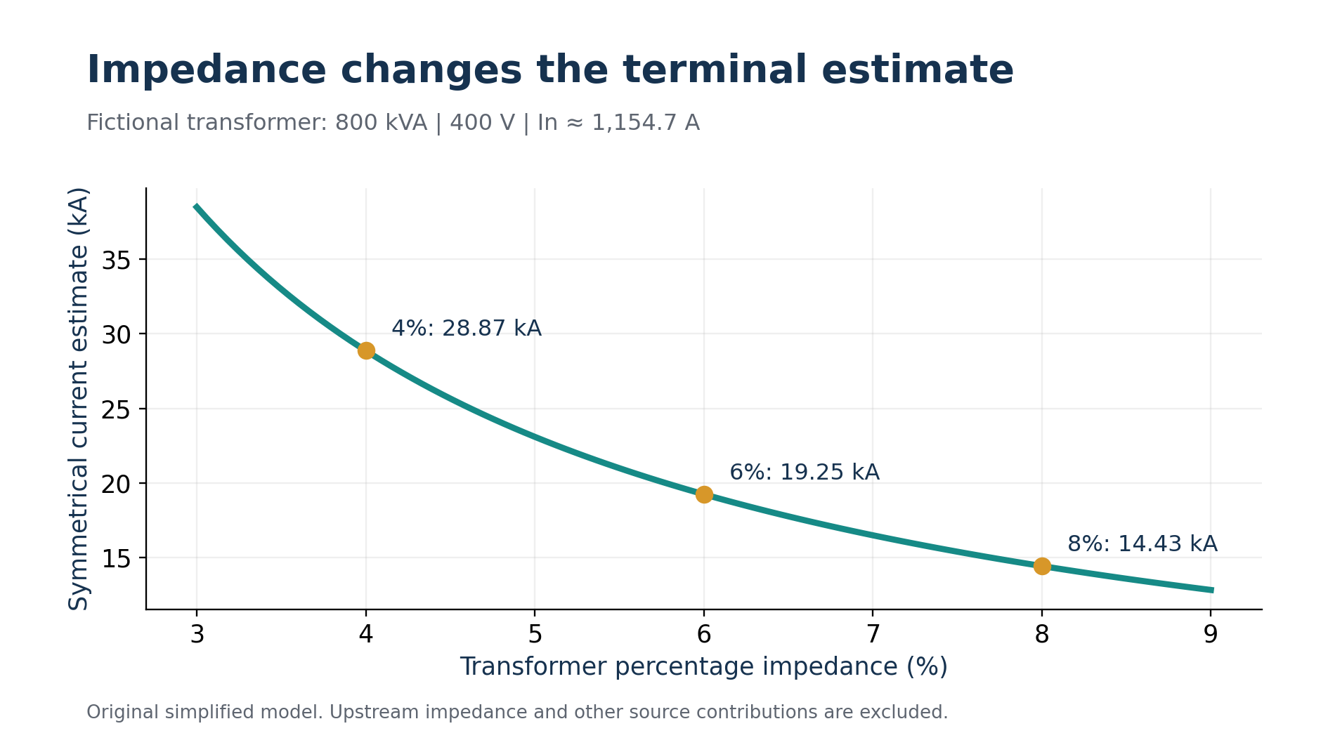
Six percent is 0.06 in per unit form. The simplified terminal current is therefore 1,154.7/0.06, approximately 19,245 amperes, or 19.25 kiloamperes. If the equation instead retains the percentage number, it becomes In × 100/6. These are two ways of expressing the same operation. [2]
Write the conversion explicitly. Dividing 1,154.7 by six without the factor of one hundred produces approximately 192.45 amperes, which is not the intended fault estimate. Dividing by 0.06 and multiplying by one hundred again creates the opposite error. Keep the equation and input convention together on the worksheet.
Attach a precise label to the result: simplified balanced three phase symmetrical fault estimate at the transformer secondary terminals, with upstream impedance neglected. That description is longer than “fault current,” but it prevents the figure from being reused for a different location or a different fault type without analysis.
Do not describe the estimate as the universal maximum current for the installation. Actual assessments can require voltage factors, transformer impedance tolerances, supply network information and contributions from other equipment. The simplified number is a starting point for understanding the scale, not a replacement for the applicable study method.
Explore sensitivity before trusting precision
Keep the fictional rating and voltage unchanged, but compare percentage impedances of four, six and eight percent. The corresponding estimates are approximately 28.87, 19.25 and 14.43 kiloamperes. These are alternative teaching cases, not three simultaneous operating states of the same transformer.
The relationship shows why copying an impedance from a different unit can matter greatly. A lower assumed impedance produces a larger prospective terminal current. The last decimal place in a calculator output is far less important than verifying the nameplate field that drives the calculation.
Now keep six percent and 400 volts, but use a fictional 1,000 kilovolt ampere rating. Rated current becomes approximately 1,443.4 amperes and the simplified terminal estimate becomes approximately 24.06 kiloamperes. This controlled comparison changes one input. It helps learners explain the direction and approximate size of a change before pressing a calculator button.
For a technical record, include input confidence. A verified nameplate and an assumed value should not look identical in the data sheet. If the impedance is unreadable or the source information is missing, state what needs confirmation. A calculation that honestly identifies a missing input is more useful than one that conceals it behind precise formatting.
Move from the terminals to the board
The connecting path introduces additional impedance. A fault at a downstream board must be assessed using the relevant source and conductor network. Schneider Electric's guide distinguishes terminal calculations from calculations at other points within a low voltage installation. Do not move a terminal result onto a remote board drawing without examining that path. [3]
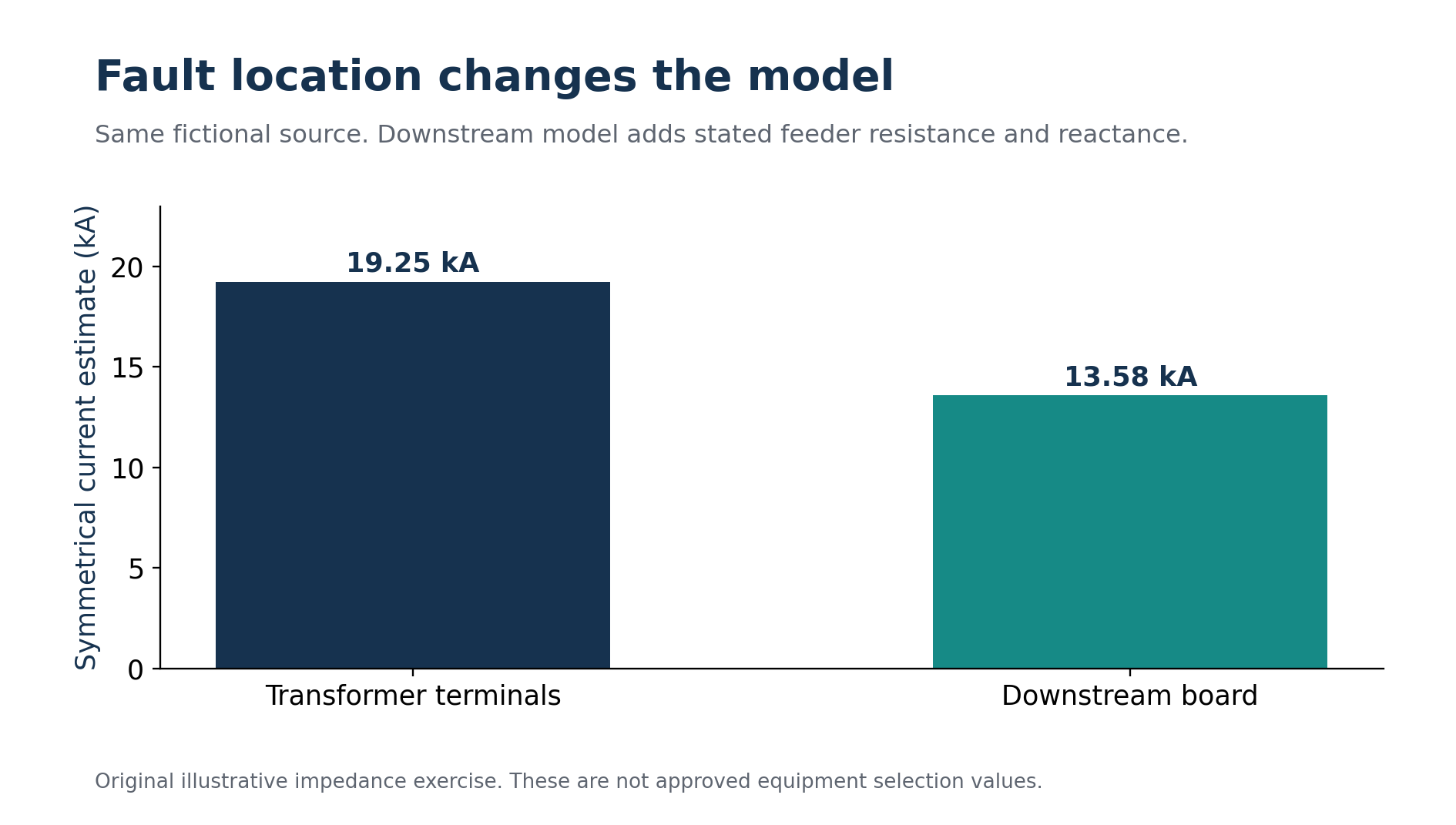
An original simplified impedance exercise illustrates the effect. Model the fictional transformer impedance entirely as reactance for this exercise. Its magnitude is 0.06 × 400²/800,000 = 0.012 ohm per phase. Assume the feeder adds 0.008 ohm resistance and 0.003 ohm reactance per phase. These are supplied teaching values rather than a physical cable specification.
The combined model has R = 0.008 ohm and X = 0.015 ohm. Its magnitude is √(0.008² + 0.015²) = 0.017 ohm. With 400/√3 volts as the phase voltage, the resulting balanced three phase estimate is approximately 13.58 kiloamperes. The extra impedance reduces the estimate relative to the terminal case.
Do not add impedance magnitudes indiscriminately. Resistance and reactance are components of a complex quantity. In this example they were combined by component before calculating the magnitude. Real studies need appropriate data for the network, transformer, conductor temperatures and source conditions rather than the simplified values used here.
Adding the supplied feeder impedance reduces the downstream estimate in the fictional model. Original chart.
Match the result to the protective question
Fault current supports several different checks. Interruption capability concerns whether the device can interrupt the relevant prospective current under its specified conditions. Short time withstand and peak withstand concern other duties. Protective operation at a lower available fault level can be a separate issue. One current number does not answer every question. [3]
Suppose a fictional purchasing note proposes a device marked 20 kiloamperes because the simplified transformer result is 19.25 kiloamperes. The closeness of those two values should prompt a complete assessment, not a casual pass. Confirm the applicable rating definition, voltage, installation location, actual fault study and any permitted coordinated arrangement before selecting equipment.
Read the manufacturer's rating terminology. Different interruption and withstand quantities are not interchangeable just because they use amperes or kiloamperes. Preserve the exact product reference and relevant data sheet. A procurement description that reduces every requirement to “a 20 kA breaker” can lose information that matters to the final design.
The clearing energy also deserves attention where required. In a hypothetical constant current model, 10,000 amperes for 0.05 second corresponds to I²t = 5,000,000 ampere squared seconds. Doubling that time doubles the calculated quantity. Actual protective devices can limit current and have specified let through behaviour, so this elementary illustration is not their performance curve.
Include the source operating states
An installation may operate with a utility transformer, a generator, parallel transformers or other contributing sources. Each credible state needs the relevant model. A generator's fault behaviour should not be obtained by substituting its rating into the simple transformer percentage impedance equation. Source characteristics and time behaviour require appropriate data. [4]
For the fictional industrial unit, define whether the replacement board is supplied by one transformer alone or can receive another source. Record normal operation, transfer operation and any permitted parallel state. Then identify which state governs each required equipment check. The state that produces the greatest interruption duty may differ from the state that makes protective operation most difficult.
Interlocks and operating restrictions belong in the design evidence if they exclude a source combination. An informal expectation that two supplies “will never run together” is not equivalent to a verified arrangement preventing that state. The fault study and the operating design should describe the same installation.
Keep different fault quantities separate
The simplified terminal result represents a symmetrical RMS quantity in the selected model. It should not be relabelled as a peak making current. A peak assessment depends on additional characteristics of the fault and the relevant method. When a data sheet lists several fault related ratings, compare like quantities and preserve their definitions. Converting amperes to kiloamperes changes a unit prefix; it does not convert RMS current into peak current or transform an interruption rating into a withstand rating. This distinction belongs in the equipment comparison rather than being left for somebody to notice after ordering.
The same discipline applies to fault type. A balanced three phase short circuit, a line to neutral fault and a line to protective conductor fault can involve different paths and different impedances. The nameplate shortcut developed here does not establish every one of those currents. In a study exercise, write the stated fault type at the top of the page. In a project review, check that the calculation set covers the faults needed for the protective questions being answered. A well labelled result can then be used for its intended purpose, while missing assessments remain visible. This prevents a single convenient figure from becoming an unexplained substitute for a complete protection review across several boards and source operating states.
Make the calculation reviewable
A useful worksheet contains the source identification, rating, voltage basis, impedance convention, calculated rated current, terminal estimate and exact point being assessed. It also contains the model assumptions and the remaining checks. Keep units visible at every stage so another person can reproduce the result without decoding a spreadsheet.
During revision, preserve the reason for each change. A new feeder length, a replacement transformer or an altered source arrangement can affect the study. Merely replacing the old number with the new number hides the design event that produced it. A brief revision note is usually enough to maintain a useful history.
For examination practice, explain the fictional 800 kilovolt ampere example aloud. Describe why the input is apparent power, why the voltage is line to line, how six percent becomes 0.06, and why the downstream estimate differs. An explanation that connects those choices shows understanding beyond memorising a compact equation.
Transformer fault calculations are valuable when their limits remain visible. Read the nameplate carefully, calculate the rated current, apply the impedance convention consistently and identify the point of fault. Then extend the model to the actual network and match its results to the equipment checks. The goal is a defensible design record, not a large number printed without context.
מקורות והפניות
המקורות המוזכרים בגוף המאמר מופיעים כאן כפי שנמסרו במקור.
- [1] Nami Academy: transformer short circuit calculator
- [2] Schneider Electric: transformer secondary terminal short circuit current
- [3] Schneider Electric: three phase short circuit current at points in an installation
- [4] Schneider Electric: generator protection
רוצים לתרגל את הנושא?
אחרי הקריאה אפשר לעבור למבחן או למדריך הקשור לנושא.