
Describe what the poles do
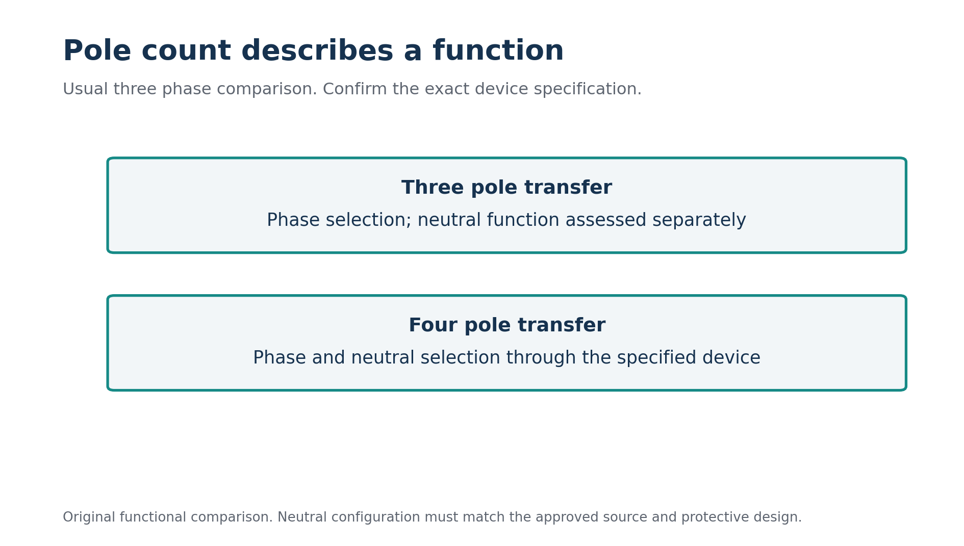
In the usual three phase changeover comparison, three poles transfer the three phase conductors. A fourth pole can transfer the neutral as well. The important difference is therefore the neutral connection through the operating states. This functional explanation should be checked against the actual device diagram and specification rather than inferred from a photograph. [2]
A solid neutral arrangement maintains a continuous neutral connection through the transfer assembly. A switched neutral arrangement uses an additional switching pole to select the relevant source neutral. ASCO also describes overlapping neutral arrangements with a particular contact sequence. These terms identify different functions, and overlapping neutral should not be treated as another name for every four pole device. [3]
Pole count does not describe every aspect of the equipment. It does not tell you the transfer sequence, contact ratings, controller behaviour, permitted source synchronisation or protective coordination. Read the complete product reference. Two devices with the same number of poles can still behave differently during transfer.
Start with a source inventory
For the fictional hall, identify the normal supply and the standby generator. Record their voltage arrangements, neutral availability and the earthing and bonding information needed by the designer. Also identify where the transfer device sits in relation to the incoming boards, protective devices and selected loads.
Do not assume the generator's factory configuration describes its final installed arrangement. The supplied equipment information and the approved project design must be reconciled. Likewise, do not infer the normal supply's complete protective arrangement from the presence of a neutral terminal at one board. Trace the relevant connections using verified documentation.
List any additional sources, such as another generator, storage system or photovoltaic equipment that can affect the arrangement. Then describe which sources can supply which loads. A transfer review that considers only two sources may be incomplete if another connection creates a credible operating state elsewhere in the installation.
Finally, identify the loads. Some need only a running power allowance; others may have continuity, starting or neutral related requirements. A lift, electronic control system and simple lighting circuit should not be treated as identical loads because they share a supply board. The transfer design needs the relevant equipment information and operating expectations.
Separate neutral from protective conductor functions
The neutral and protective arrangements must be identified by function. A conductor carrying normal return current and a conductor providing a protective connection have different roles. Combined conductor arrangements introduce further questions. Colour or a shorthand label cannot replace verification of the actual function at the point being assessed.
Create a conceptual source diagram for review, showing the source neutral connections, relevant bonding points, protective connections and load neutral route. Keep it separate from a construction drawing until the design is established. Its purpose is to expose questions that a simple transfer symbol can hide.
For each proposed device, ask which connections exist with the normal source selected, with the standby source selected and during transfer. Then ask whether those connections agree with the intended earthing and fault protection arrangement. This physical review is more informative than repeating a slogan about generators always needing one particular pole count.
The answer depends on the actual design and applicable Israeli requirements. Do not import a foreign code's source classification or wiring rule as an automatic local instruction. Manufacturer application material can explain concepts while the responsible professional establishes the jurisdictional requirements and approved arrangement for the project.
Review the transfer states explicitly
Use a state record rather than a single static picture. The hall's first state has the normal source supplying the selected loads. The second has the standby source supplying them. The third describes the transition between those states. For each, identify the active phase path, neutral arrangement and protective assumptions.
Review the operating and protective paths during normal supply, transfer and standby supply. Original concept diagram.
If the proposed transfer is open transition, establish the specified interruption sequence and how the neutral contacts behave. If another transition method is proposed, obtain its exact description and required source conditions. The word “automatic” describes control action; it does not describe whether sources overlap or whether the neutral remains connected.
ASCO's descriptions distinguish a switched neutral sequence from an overlapping neutral sequence. That distinction illustrates why a diagram needs time information as well as connection information. The relevant contact operation must be confirmed for the selected equipment rather than borrowed from a different transfer switch family. [3]
Ask what happens if the normal source fails in an unusual way, the standby source is unavailable or the controller loses its required supply. The answers come from the device and system design, not from its pole count. Record the expected operating behaviour and any limitation that affects the loads or protective arrangement.
Follow the fault return path in each state
After drawing the normal operating paths, examine the protective paths for the relevant faults. A change in source can change the available fault current and the route back to that source. A protective device selected using only the normal supply conditions may require another assessment under standby operation.
In the fictional hall, imagine the normal source provides a fault level that readily supports one protective assessment, while the generator's available current behaves differently. The design review needs the appropriate generator data and protective characteristics. A transformer terminal calculation cannot simply be reused as a generator fault calculation. [4]
The neutral arrangement can also interact with residual current sensing and bonding connections. Trace the relevant monitored conductors and return paths in the actual proposed system. Identify unintended parallel paths or connections that would undermine the intended protective explanation. Do not diagnose their presence from a generic diagram that does not represent the project.
For a study exercise, compare two supplied conceptual arrangements and describe their paths. Stop short of declaring a real wiring solution without the necessary source and regulatory information. A strong answer identifies what must be known and explains why each missing fact affects the choice.
אחרי הלמידה, עברו למבחן הרלוונטי וראו אילו שאלות עדיין דורשות חיזוק.