
Read the three essential inputs
The transformer apparent power rating is usually expressed in kilovolt amperes. It describes an electrical rating and should not be treated as a kilowatt figure with an assumed power factor. The secondary voltage used in the three phase rated current equation is the line to line value. Record the nameplate wording and the voltage basis before substituting numbers.
Percentage impedance, often written uk or Usc, describes the transformer impedance through a percentage quantity. It is not the normal percentage voltage lost in a downstream cable. Entering six percent as either six or 0.06 depends on the chosen equation. Both conventions can work, but mixing them produces an error of a hundred.
Also record which transformer the data describes. A project may contain several units with similar enclosures but different ratings or impedance values. A photograph should include readable identification as well as the numerical fields. An unlabelled note saying “800, 400, 6” cannot establish that the correct transformer has been assessed.
Calculate rated secondary current first
For a three phase transformer, the rated secondary line current is In = S/(√3 × U), using apparent power in volt amperes and line to line voltage in volts. In the simplified terminal fault calculation, prospective symmetrical current is then estimated as In divided by the per unit impedance. Schneider Electric presents this method assuming negligible upstream network impedance. [2]
Use an original fictional transformer rated at 800 kilovolt amperes, with a 400 volt secondary basis and six percent impedance. Convert the power to 800,000 volt amperes. Rated current is 800,000/(√3 × 400), approximately 1,154.7 amperes. This intermediate result should be recorded separately from the fault estimate.
Rated current describes the transformer's rating under the model. It is not its fault current and is not automatically the current drawn by the connected installation. A partly loaded transformer can have a normal operating current below this value while still being associated with a substantial prospective short circuit current.
Check the scale before continuing. If the calculation gives 1.15 amperes, inspect the kilovolt ampere conversion. If it gives around three times the expected value, inspect the voltage definition and three phase relationship. A simple rated current check can prevent an input error from being amplified in the next step.
Use percentage impedance consistently
Six percent is 0.06 in per unit form. The simplified terminal current is therefore 1,154.7/0.06, approximately 19,245 amperes, or 19.25 kiloamperes. If the equation instead retains the percentage number, it becomes In × 100/6. These are two ways of expressing the same operation. [2]
Write the conversion explicitly. Dividing 1,154.7 by six without the factor of one hundred produces approximately 192.45 amperes, which is not the intended fault estimate. Dividing by 0.06 and multiplying by one hundred again creates the opposite error. Keep the equation and input convention together on the worksheet.
Attach a precise label to the result: simplified balanced three phase symmetrical fault estimate at the transformer secondary terminals, with upstream impedance neglected. That description is longer than “fault current,” but it prevents the figure from being reused for a different location or a different fault type without analysis.
Do not describe the estimate as the universal maximum current for the installation. Actual assessments can require voltage factors, transformer impedance tolerances, supply network information and contributions from other equipment. The simplified number is a starting point for understanding the scale, not a replacement for the applicable study method.
Explore sensitivity before trusting precision
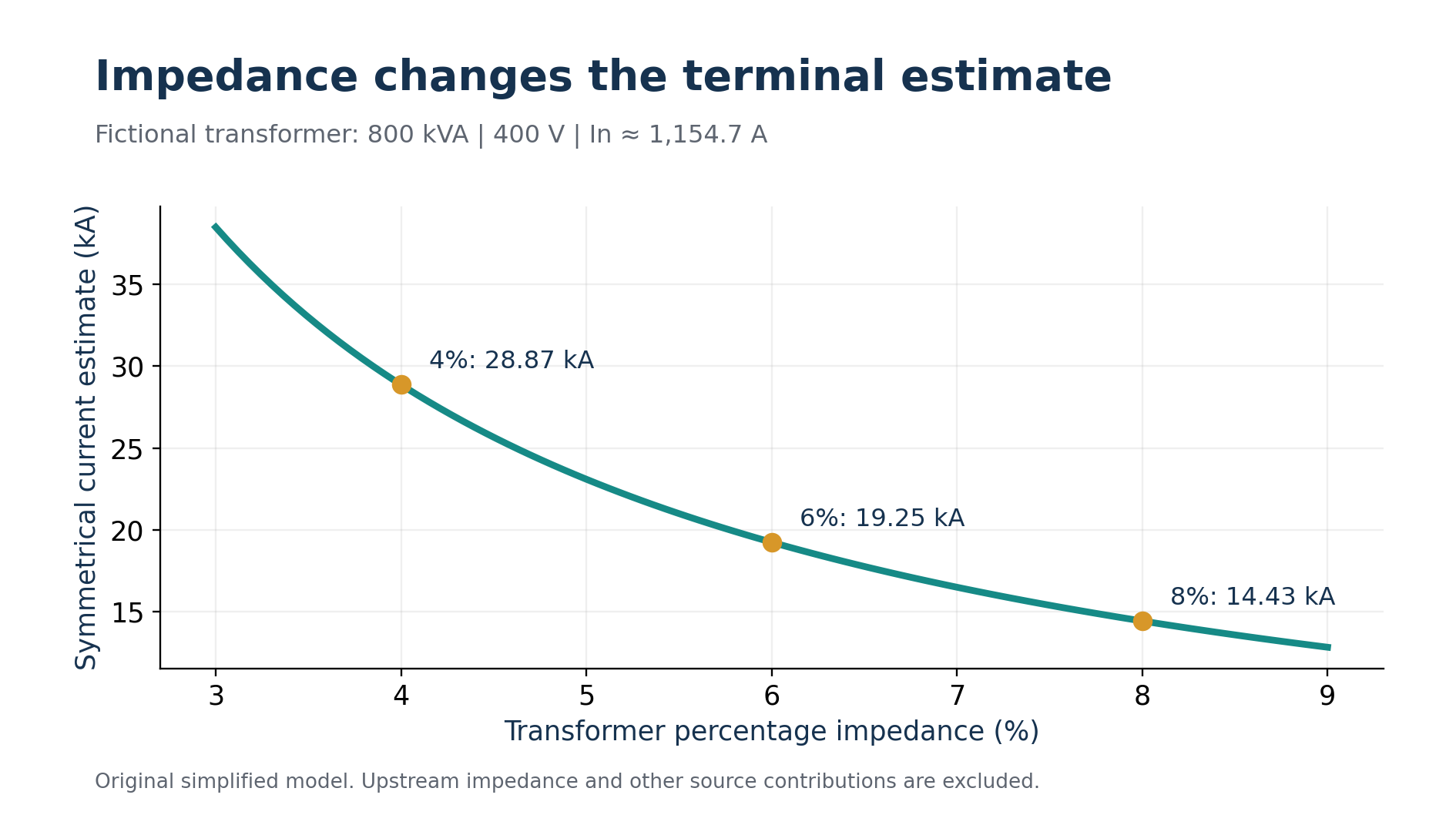
Keep the fictional rating and voltage unchanged, but compare percentage impedances of four, six and eight percent. The corresponding estimates are approximately 28.87, 19.25 and 14.43 kiloamperes. These are alternative teaching cases, not three simultaneous operating states of the same transformer.
The relationship shows why copying an impedance from a different unit can matter greatly. A lower assumed impedance produces a larger prospective terminal current. The last decimal place in a calculator output is far less important than verifying the nameplate field that drives the calculation.
Now keep six percent and 400 volts, but use a fictional 1,000 kilovolt ampere rating. Rated current becomes approximately 1,443.4 amperes and the simplified terminal estimate becomes approximately 24.06 kiloamperes. This controlled comparison changes one input. It helps learners explain the direction and approximate size of a change before pressing a calculator button.
For a technical record, include input confidence. A verified nameplate and an assumed value should not look identical in the data sheet. If the impedance is unreadable or the source information is missing, state what needs confirmation. A calculation that honestly identifies a missing input is more useful than one that conceals it behind precise formatting.
Move from the terminals to the board
The connecting path introduces additional impedance. A fault at a downstream board must be assessed using the relevant source and conductor network. Schneider Electric's guide distinguishes terminal calculations from calculations at other points within a low voltage installation. Do not move a terminal result onto a remote board drawing without examining that path. [3]
An original simplified impedance exercise illustrates the effect. Model the fictional transformer impedance entirely as reactance for this exercise. Its magnitude is 0.06 × 400²/800,000 = 0.012 ohm per phase. Assume the feeder adds 0.008 ohm resistance and 0.003 ohm reactance per phase. These are supplied teaching values rather than a physical cable specification.
The combined model has R = 0.008 ohm and X = 0.015 ohm. Its magnitude is √(0.008² + 0.015²) = 0.017 ohm. With 400/√3 volts as the phase voltage, the resulting balanced three phase estimate is approximately 13.58 kiloamperes. The extra impedance reduces the estimate relative to the terminal case.
Do not add impedance magnitudes indiscriminately. Resistance and reactance are components of a complex quantity. In this example they were combined by component before calculating the magnitude. Real studies need appropriate data for the network, transformer, conductor temperatures and source conditions rather than the simplified values used here.
Adding the supplied feeder impedance reduces the downstream estimate in the fictional model. Original chart.
אחרי הלמידה, עברו למבחן הרלוונטי וראו אילו שאלות עדיין דורשות חיזוק.